Welcome to Model of the Support
The model is very simple and consists of three 1-brunching elements (see the Figure down below), which serve as the velocity nodes (see effort branches). The left 1-branch serves as a node of the x component of point O velocity, and the middle one as the corresponding y-component. As the point of rotation O is fixed, two source flows SF are connected to these nodes at the power-in ports by the bonds, and the corresponding flows are set to zero. The third 1-branch is the node of angular velocity ω. Generally speaking, there is friction between the rod and support around the rotation axis. We may model it by a Source Effort SF connected by a bond to the corresponding power-in port. We will simplify the model by setting the generated friction torque equal to zero, i.e. we assume a frictionless rotation. To access the angular velocity of the last 1-branch we insert an output control port in the element, and connect it to the document output port by a signal (see the Figure below). For more details on sources see effort and flow sources.
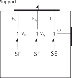
Every 1-junction has a power-out port to which the pair of effort and flow variables are associated: FOx and
vOx, FOy and vOy, as well the torque T and angular velocity ω (see effort and flow variables at rotation point O). Thus the Support's power port variables
consists of a pair of the efforts and flows lists:
e = (FOx, FOy, T), and
f =
(vOx, vOy, ω).
These lists can be written either horizontally or vertically. But, only the order of the variables in the lists matters.
Next Back